02.120.0851: Blank at Bearing Wall - Top of Wall This detail shows a precast concrete plank bearing at the top of an exterior CMU wall. The wall has horizontal joint reinforcement at 16" o.c. vertically. The plank has continuous reinforcement and grout at the keyways, tying the floor to the wall with bent bars. The [...]
02.120.0752: Plank at Bearing Wall - Interior Wall, Intermediate Elev. This detail shows a precast concrete plank bearing at an interior CMU wall. The wall has horizontal joint reinforcement at 16" o.c. vertically. The plank has continuous reinforcement and grout at the keyways, and the floor bears on an interior CMU bond beam. The wall [...]
02.120.0713: Floor Connection Detail - Option 3 This hybrid masonry and steel floor connection detail shows a composite floor deck supported by open web steel joists bearing on a steel beam supported by a CMU wall as part of the hybrid masonry and steel structural system. DOWNLOAD DETAILDynamic 3D Detail Explore Detail
02.120.0712: Floor Connection Detail - Option 2 This hybrid masonry and steel floor connection detail shows a composite floor deck supported by laterally braced steel beams supported by a CMU wall as part of the hybrid masonry and steel structural system. DOWNLOAD DETAILDynamic 3D Detail Explore the detail and download the Sketchup Model in the [...]
02.120.0702: Floor Detail - Hybrid Type IIB This hybrid masonry and steel floor connection detail makes use of bent reinforcement to tie the the floor to the wall. DOWNLOAD DETAILDynamic 3D Detail Explore the detail and download the Sketchup Model in the 3D Warehouse. Explore Detail
02.120.0701: Floor Detail - Hybrid Type I & IIa This hybrid masonry and steel floor connection detail makes use of weldable reinforcement to tie the the floor to the wall. DOWNLOAD DETAILDynamic 3D Detail Explore Detail
02.010.0801: Masonry Wall Cap - Single Wythe CMU This detail shows a concrete masonry (CMU) wall, top of wall detail. The wall cap is anchored to the grouted wall with a vertical dowel through the flashing, which is then sealed around the dowel penetration. The flashing is shown as a flexible material for the through-wall [...]
This site uses cookies
Small text files that are placed on your machine to help the site provide a better user experience. In general, cookies are used to retain user preferences, store information for things like shopping carts, and provide anonymised tracking data to third party applications like Google Analytics. As a rule, cookies will make your browsing experience better. However, you may prefer to disable cookies on this site and on others. The most effective way to do this is to disable cookies in your browser. We suggest consulting the Help section of your browser or if you decline you will be redirected to the About Cookies website which offers guidance for all modern browsers.
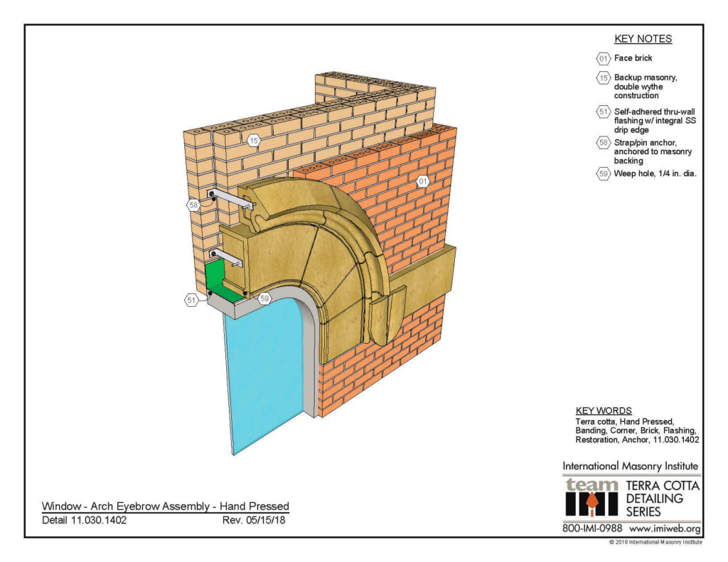 11.030.1402: Window - Arch Eyebrow Assembly - Hand Pressed DOWNLOAD DETAIL
  11.030.0812: Parapet Corner Assembly, Hand Pressed DOWNLOAD DETAIL
 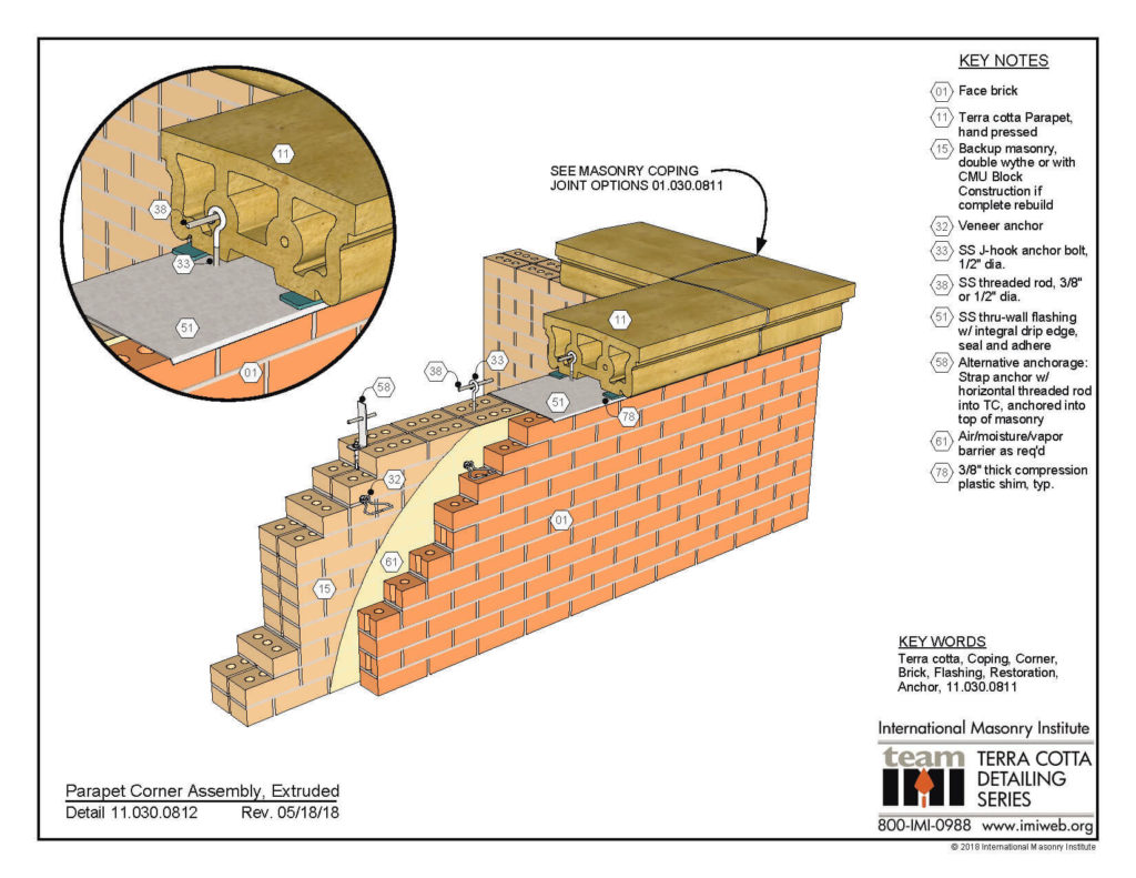 11.030.0811: Parapet Corner Assembly, Extruded DOWNLOAD DETAIL
 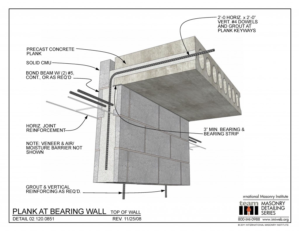 02.120.0851: Blank at Bearing Wall - Top of Wall This detail shows a precast concrete plank bearing at the top of an exterior CMU wall. The wall has horizontal joint reinforcement at 16" o.c. vertically. The plank has continuous reinforcement and grout at the keyways, tying the floor to the wall with bent bars. The [...]
 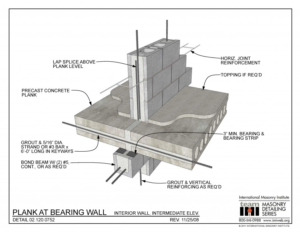 02.120.0752: Plank at Bearing Wall - Interior Wall, Intermediate Elev. This detail shows a precast concrete plank bearing at an interior CMU wall. The wall has horizontal joint reinforcement at 16" o.c. vertically. The plank has continuous reinforcement and grout at the keyways, and the floor bears on an interior CMU bond beam. The wall [...]
 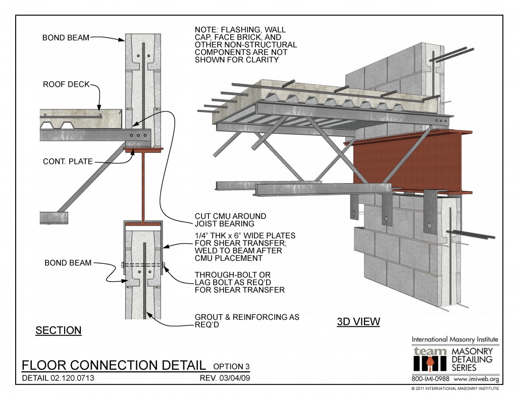 02.120.0713: Floor Connection Detail - Option 3 This hybrid masonry and steel floor connection detail shows a composite floor deck supported by open web steel joists bearing on a steel beam supported by a CMU wall as part of the hybrid masonry and steel structural system. DOWNLOAD DETAILDynamic 3D Detail Explore Detail
 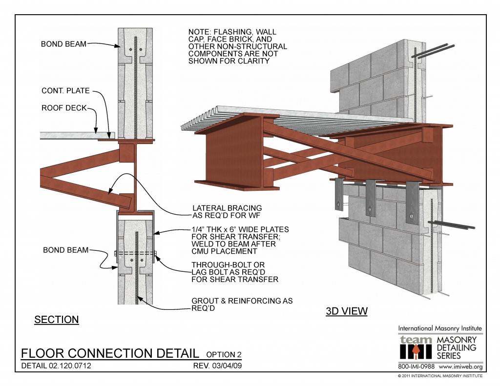 02.120.0712: Floor Connection Detail - Option 2 This hybrid masonry and steel floor connection detail shows a composite floor deck supported by laterally braced steel beams supported by a CMU wall as part of the hybrid masonry and steel structural system. DOWNLOAD DETAILDynamic 3D Detail Explore the detail and download the Sketchup Model in the [...]
 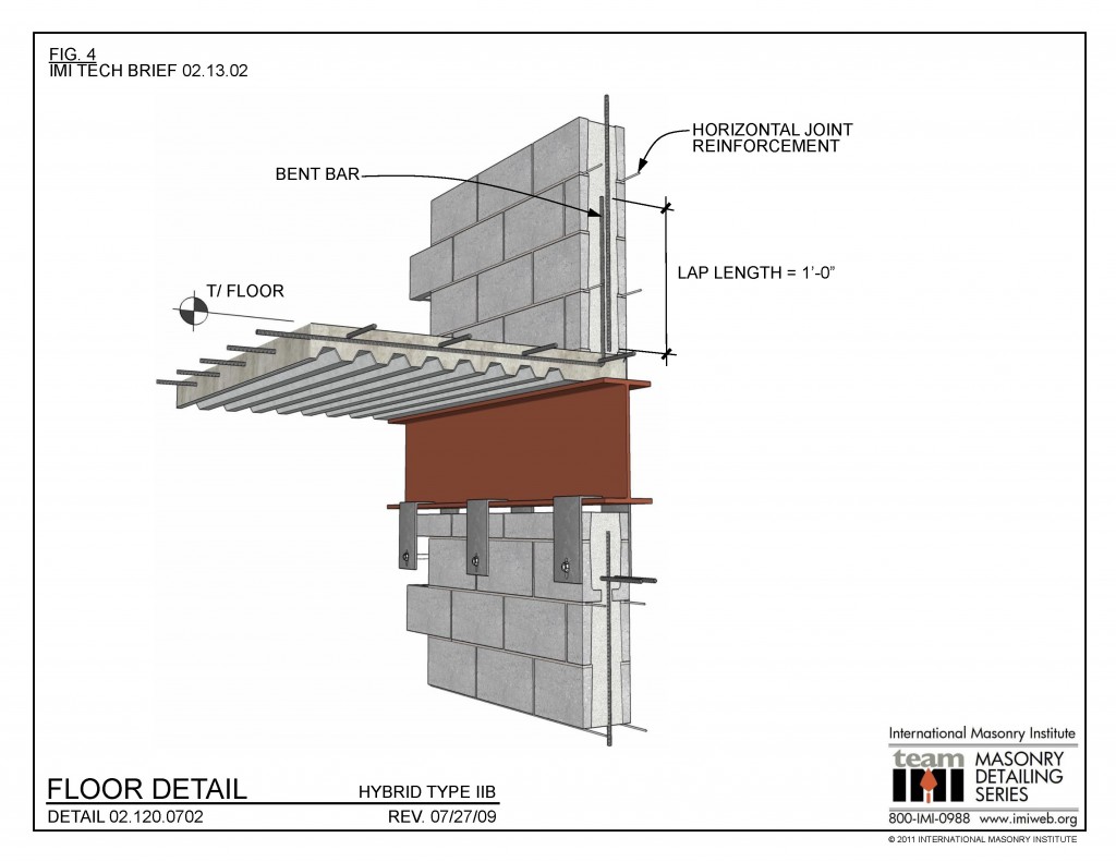 02.120.0702: Floor Detail - Hybrid Type IIB This hybrid masonry and steel floor connection detail makes use of bent reinforcement to tie the the floor to the wall. DOWNLOAD DETAILDynamic 3D Detail Explore the detail and download the Sketchup Model in the 3D Warehouse. Explore Detail
  02.120.0701: Floor Detail - Hybrid Type I & IIa This hybrid masonry and steel floor connection detail makes use of weldable reinforcement to tie the the floor to the wall. DOWNLOAD DETAILDynamic 3D Detail Explore Detail
 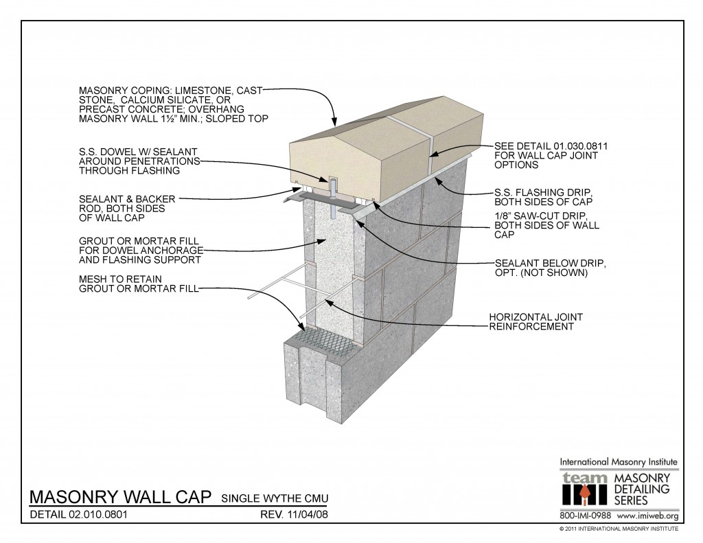 02.010.0801: Masonry Wall Cap - Single Wythe CMU This detail shows a concrete masonry (CMU) wall, top of wall detail. The wall cap is anchored to the grouted wall with a vertical dowel through the flashing, which is then sealed around the dowel penetration. The flashing is shown as a flexible material for the through-wall [...]